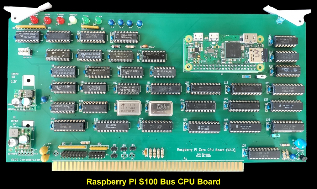
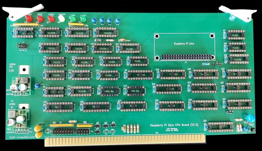
Raspberry Pi CPU Board
(V2.3)
KiCAD Folder
(.zip
File) V1.0 (8/8/2022)
Raspberry Pi CPU Board
(V2.3) Layout (pdf format)
V1.0 (8/19/2022)
(Supplied by Rick Bromagem)
Raspberry Pi CPU Board
(V2.3) BOM
(pdf format)
V1.0 (8/19/2022)
(Supplied by Rick Bromagem)
Raspberry Pi CPU Board (V2.3) BOM (xls format)
V1.0 (8/19/2022)
(Supplied by Rick Bromagem)
Raspberry Pi CPU Board
Gerber Files
(.zip
File) V1.0 (8/8/2022)
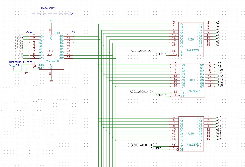
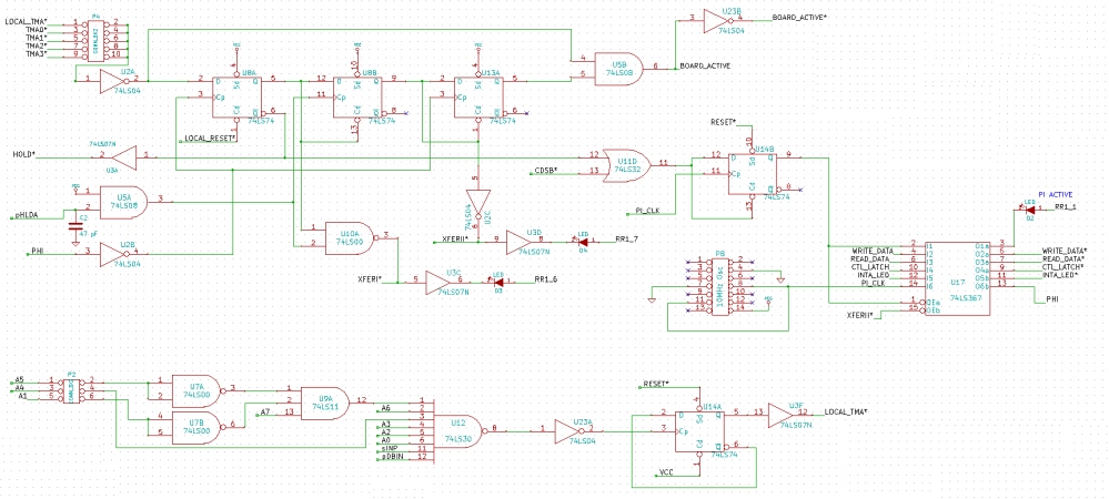
Raspberry Pi CPU Board
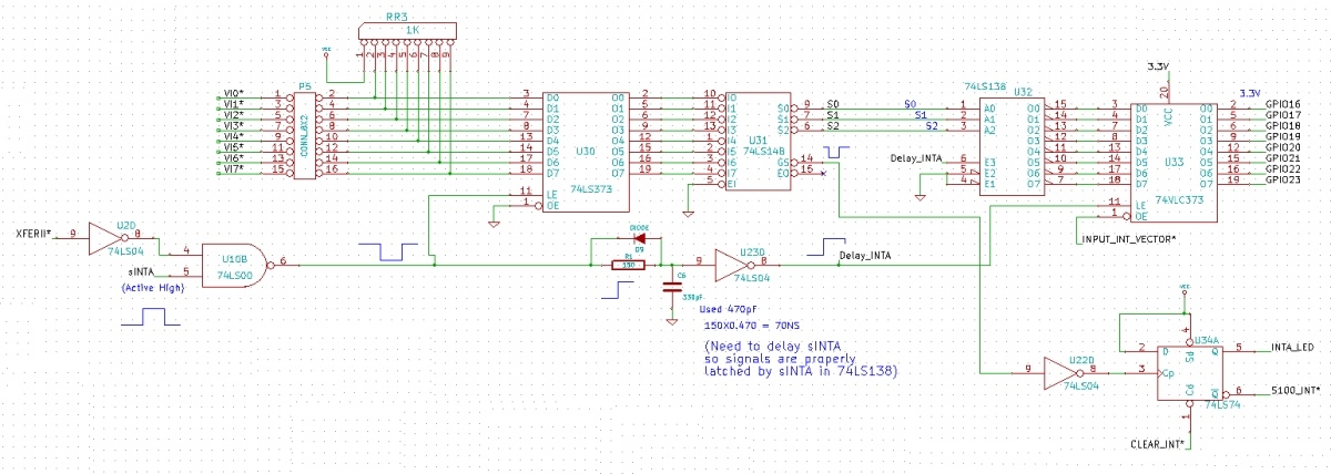
Schematic
(.Pdf
File) V1.0 (8/8/2022)
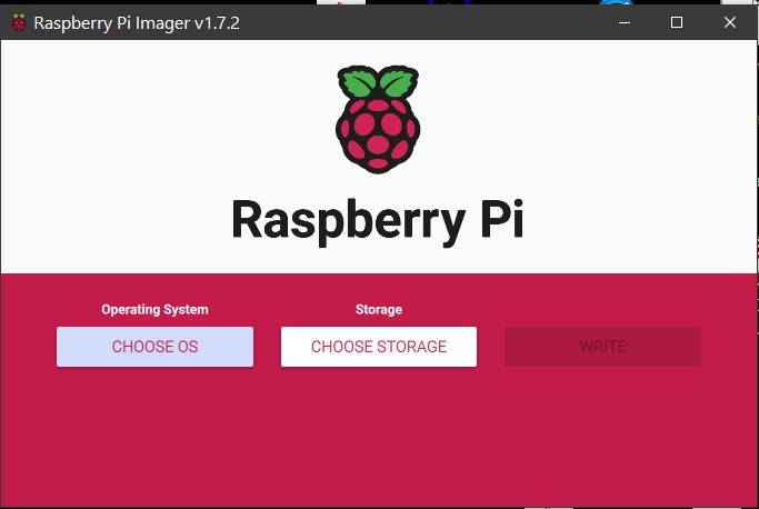
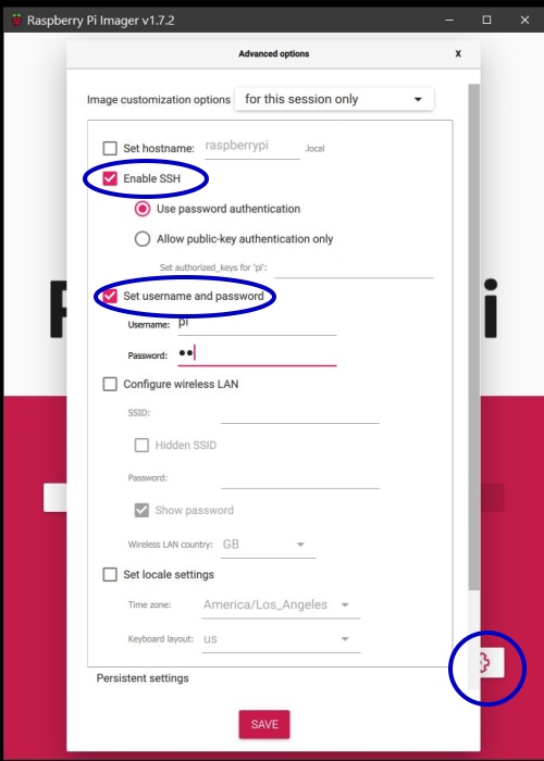
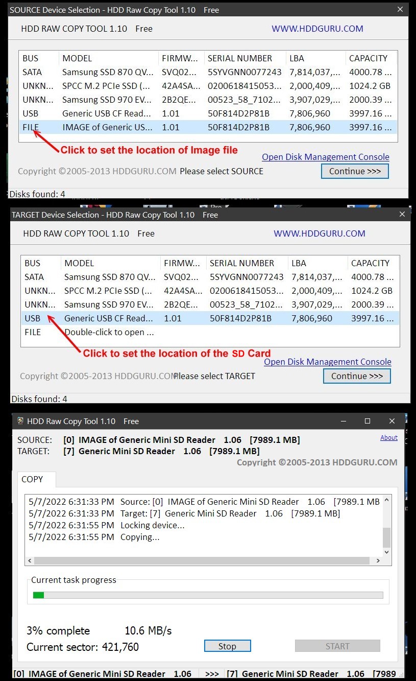
Raspberry Pi SD Card Image V1.0 (8/8/2022)
(Note this is a very large file, it will take
>30 minutes to download)
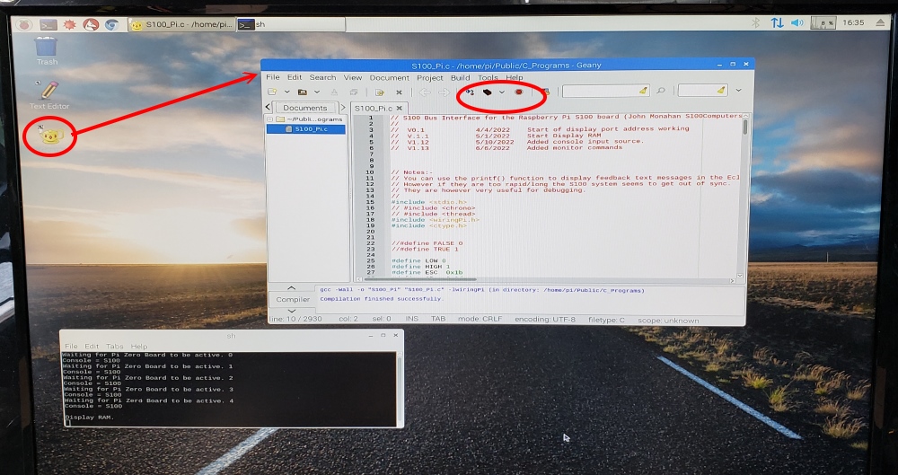
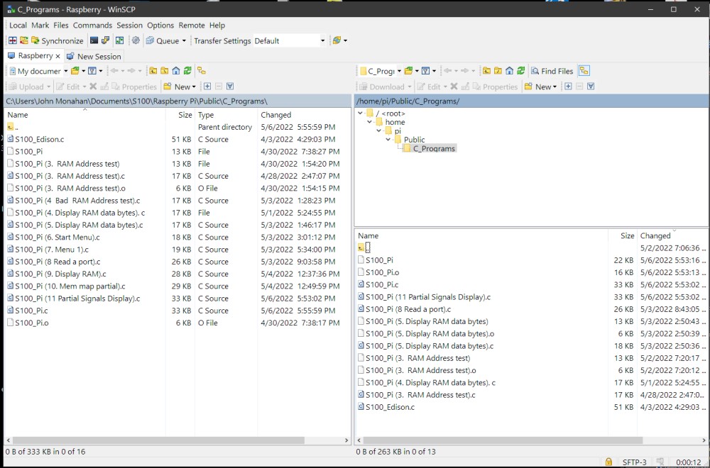
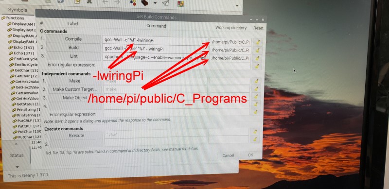
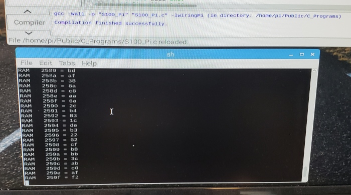
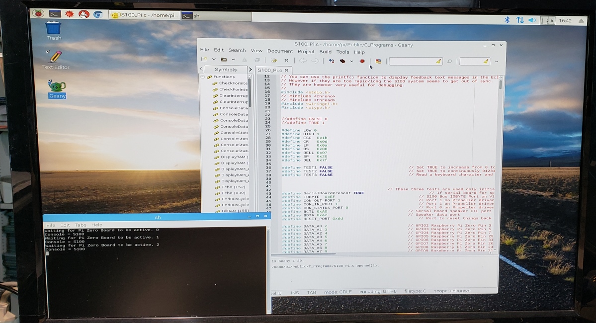
Raspberry Pi CPU C Code (Text
File)
V1.0 (8/8/2022)
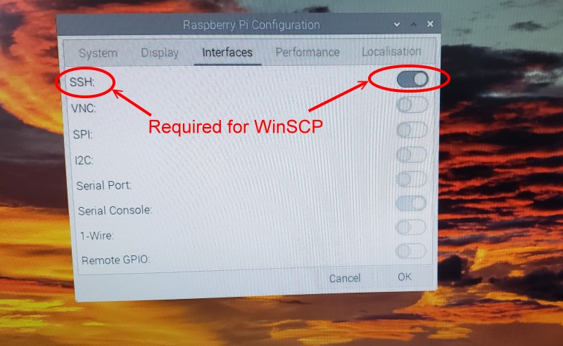
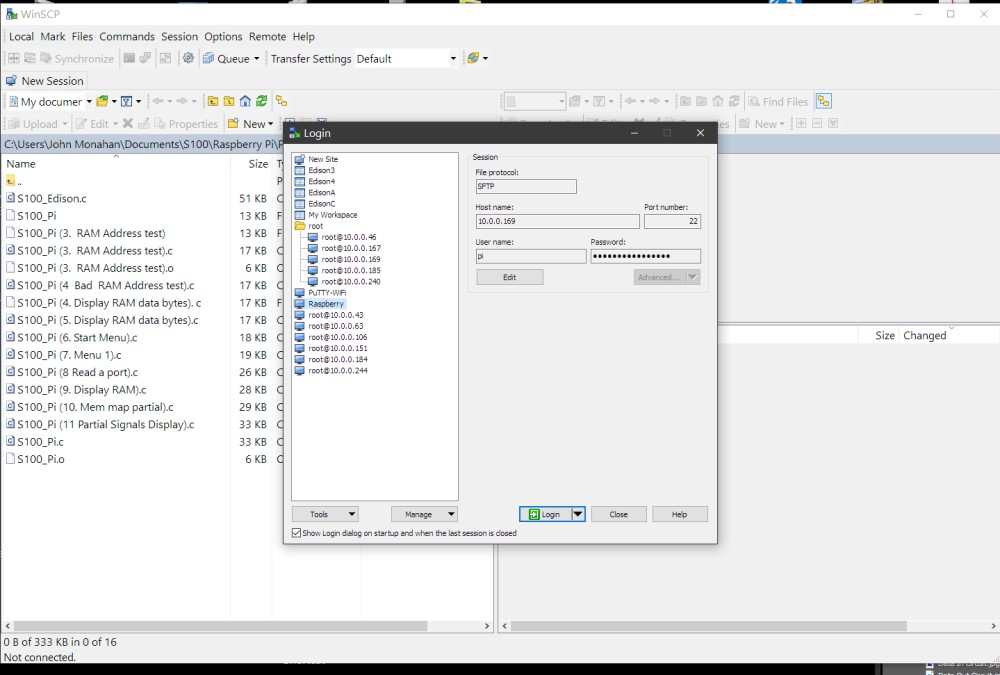
WinSCP download for Windows (64 Bit)
V1.0 (8/8/2022)
Other pages describing my S-100 hardware and software.
Please click here to continue...This page was last modified on
09/13/2022